
A tool snaps in the middle of a run. The operator does what feels responsible and dials the feed back twenty percent to be safe. The next tool lasts even less time.
This happens in shops every day, and it happens because feed rate feels like a risk setting instead of what it actually is, a cutting condition. Chip load is the number underneath that feed rate, and it decides whether your cutting edge is removing material or grinding itself away against the workpiece.
In this post we cover what chip load is, how to calculate it, why too little is more dangerous than too much, how chip thinning changes the math at light stepovers, and what your chips are telling you before the tool ever fails.
What Is Chip Load in Machining?
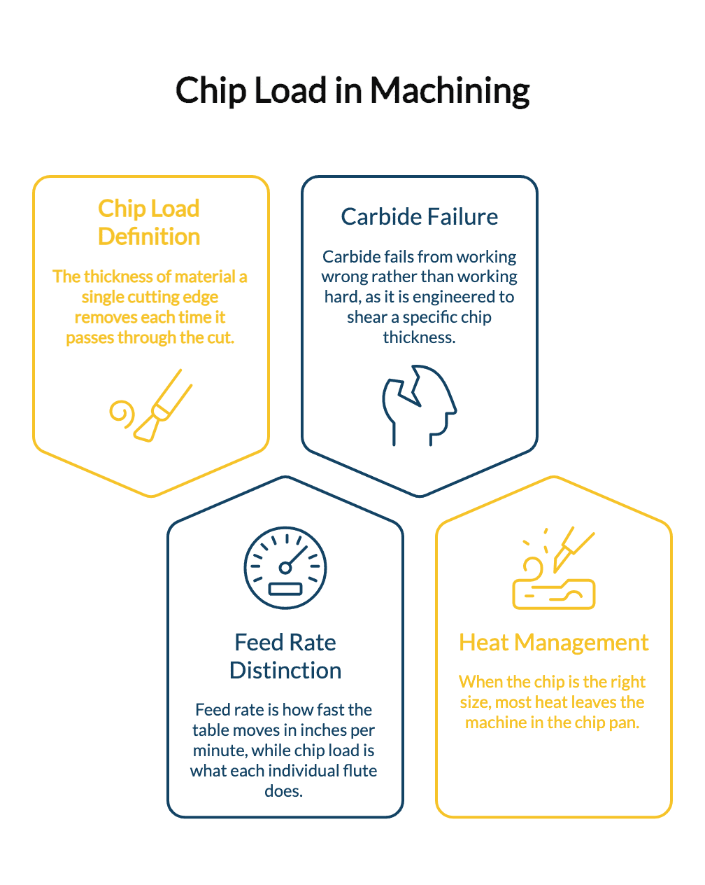
Chip load, also called feed per tooth or IPT, is the thickness of material a single cutting edge removes each time it passes through the cut.
It is not feed rate. Feed rate is how fast the table moves in inches per minute. Chip load is what each individual flute is being asked to do inside that movement. Two machines running identical feed rates can be putting completely different loads on the cutting edge depending on spindle speed and flute count.
That distinction matters because carbide does not fail from working hard. It fails from working wrong. A cutting edge is engineered to shear a chip of a specific thickness, and it wants heat to leave the cut inside that chip. When the chip is the right size, most of the heat walks out of the machine in the chip pan. When it is not, the heat stays in the edge.
The Chip Load Formula and How It Connects to SFM
The math is simple:
Feed Rate (IPM) = RPM x Number of Flutes x Chip Load (IPT)
Rearranged to find what you are actually running:
Chip Load (IPT) = Feed Rate (IPM) / (RPM x Number of Flutes)
Chip load never stands on its own. It sits directly downstream of surface speed, which sets your RPM in the first place:
RPM = (SFM x 3.82) / Tool Diameter
If you are not confident on the first half of that chain, our breakdown of SFM in machining walks through cutting speed and where the numbers come from. Get surface speed right first, then set chip load. Reversing that order is how shops end up with a feed rate that looks reasonable on paper and destroys tools in practice.
One practical warning on flute count. If you swap a 3 flute cutter for a 4 flute cutter and leave the feed rate alone, you just cut your chip load by twenty five percent without touching a single setting on the control.
Why Too Little Chip Load Destroys Tools Faster Than Too Much
This is the part that gets learned the expensive way.
When chip load drops below the minimum the edge needs to shear material, the tool stops cutting and starts rubbing. The edge burnishes the surface instead of lifting a chip. Nothing carries the heat away, so it goes straight into the carbide and straight into the part.
What follows:
- Work hardening. The rubbed surface hardens ahead of the tool, so the next pass is cutting a harder material than the one on the print. This is severe in stainless and brutal in nickel based alloys. Our post on machining Inconel and nickel based superalloys covers how fast that spiral turns expensive.
- Rapid flank wear. Heat concentrated at the edge accelerates wear and takes the coating with it.
- Poor finish, not better finish. Operators often reduce feed chasing surface quality. Below the rubbing threshold, finish gets worse, not better.
- Sudden failure. A glazed, heat damaged edge does not wear down gracefully. It lets go.
Too much chip load also fails, of course, through edge chipping, deflection, and outright breakage. The difference is that too much chip load fails loudly and gets corrected immediately. Too little fails quietly and gets repeated for months.
If tools are disappearing on you and the cause is not obvious, our guide to why carbide end mills keep breaking works through the other common culprits.
Chip Thinning: Why Your Numbers Stop Working at Light Stepovers
Here is where good numbers still produce bad results.
When radial engagement drops below half the tool diameter, the actual chip produced is thinner than the chip load you programmed. The cutting edge sweeps through a shallower arc, so it never reaches full commanded thickness. You programmed 0.003 and the edge is seeing 0.0018.
At light stepovers, running the book number puts you straight into the rubbing zone described above. The fix is to compensate:
Adjusted Chip Load = Programmed Chip Load / √(1 – (1 – 2ae/D)²)
Where ae is radial depth of cut and D is tool diameter.
At a 10 percent stepover, that factor is roughly 1.67. The same cutter that wanted 0.003 at half diameter engagement wants about 0.005 at 10 percent engagement to produce the same real chip. This is exactly why high speed toolpaths with small radial engagement run feed rates that look reckless and are not.
The same principle drives high feed milling. Those cutters use a very shallow lead angle so the chip thins dramatically, which is what lets them run feed rates several times higher than a conventional cutter at light depths of cut. Our high feed milling cutters are built around that geometry, and the chip load rules for them are not the rules for a standard end mill.
Starting Chip Load Ranges by Material
These are common starting points for solid carbide end mills at roughly half inch diameter. Always confirm against the manufacturer data for the specific tool, then adjust for your setup.
| Material | Starting Chip Load (IPT) | Notes |
|---|---|---|
| Aluminum | 0.004 to 0.008 | Needs open flutes and chip clearance more than it needs restraint |
| Mild steel | 0.002 to 0.004 | Forgiving, good place to learn the feel |
| Stainless steel | 0.0015 to 0.003 | Stay above the rubbing threshold or it work hardens |
| Titanium | 0.001 to 0.003 | Heat management is the whole problem |
| Hardened die steel, 45 HRC and up | 0.0005 to 0.0015 | Light and consistent, no interruptions |
Scale these with diameter. A 1/8 inch cutter cannot take the same chip as a 1/2 inch cutter, because the shank cannot survive the bending load. As a rough guide, chip load scales down roughly with diameter, so an eighth inch tool in steel is often in the 0.0005 to 0.001 range.
Extended reach changes things again. A tool hanging out four diameters deflects under load, and deflection means the programmed chip load is not the chip load the edge is seeing. When reach is unavoidable, the answer is usually a stub or a custom length rather than a slower feed.
Read Your Chips Before You Trust Your Numbers
The chip pan is a live readout, and it is more reliable than any calculator.
- Tight, consistent curls with some colour in steel. Correct. Blue or straw coloured chips in steel mean heat is leaving in the chip, which is the goal.
- Fine powder or dust. Chip load is too low. The tool is rubbing. Increase feed before the edge glazes.
- Long stringy chips wrapping the tool. Chip evacuation problem, usually too many flutes for the material or not enough clearance.
- Chips welding to the flutes in aluminum. Speed or coolant issue, and often a flute count that is trapping material rather than clearing it.
- Uneven chips from a multi flute cutter. This one is not a chip load problem at all. It means one flute is taking more than its share, which points at runout in the holder.
That last one is worth flagging, because it is the case where perfect chip load math still produces bad results. If only two flutes of a four flute cutter are truly engaged, your real chip load is double what you calculated no matter how careful the arithmetic was.
Getting Chip Load Right Is Cheaper Than Replacing Tools
The takeaways worth keeping:
- Chip load is the thickness each flute removes, not the feed rate on the control.
- Set surface speed and RPM first, then set feed per tooth.
- Too light is more destructive than too heavy, because rubbing generates heat the chip cannot carry away.
- Compensate for chip thinning any time radial engagement drops below half the tool diameter.
- Change flute count and you have changed your chip load, whether you meant to or not.
- The chips in the pan tell you the truth faster than the spreadsheet does.
There is also a limit to what numbers can fix. When a part demands a reach, a corner radius, or a flute geometry that no standard tool provides, dialling the feed will not close that gap. We grind solid carbide tools on 5 and 6 axis CNC equipment right here in Stoney Creek, using sub micron carbide grades, and we supply Millstar, YesTool, CERATIZIT, Kojex, and YMW lines from the same floor. For shops across Hamilton, Burlington, and the GTA, that means a custom geometry or a replacement does not have to cross a border to reach your machine.
Running into tool life you cannot explain? Contact us and we will work through the application with you.
Frequently Asked Questions
What is a good chip load for a 1/2 inch carbide end mill in steel?
A common starting point for mild steel is 0.002 to 0.004 inches per tooth, with stainless running slightly lighter at 0.0015 to 0.003. Treat these as starting values, confirm them against the tool manufacturer data, and adjust based on rigidity, reach, and the chips you are producing.
Is it better to run chip load too low or too high?
Too low is the more damaging error. A chip load below the minimum needed to shear material causes the edge to rub instead of cut, which drives heat into the carbide and work hardens the surface ahead of the tool. Too high tends to chip the edge, which is easier to spot and correct before it costs you a run of parts.
Do I need to change chip load when I change stepover?
Yes. Once radial engagement falls below half the tool diameter, chip thinning means the real chip is thinner than what you programmed, and feed needs to increase to compensate. At a 10 percent stepover the adjustment is roughly 1.67 times the base chip load.