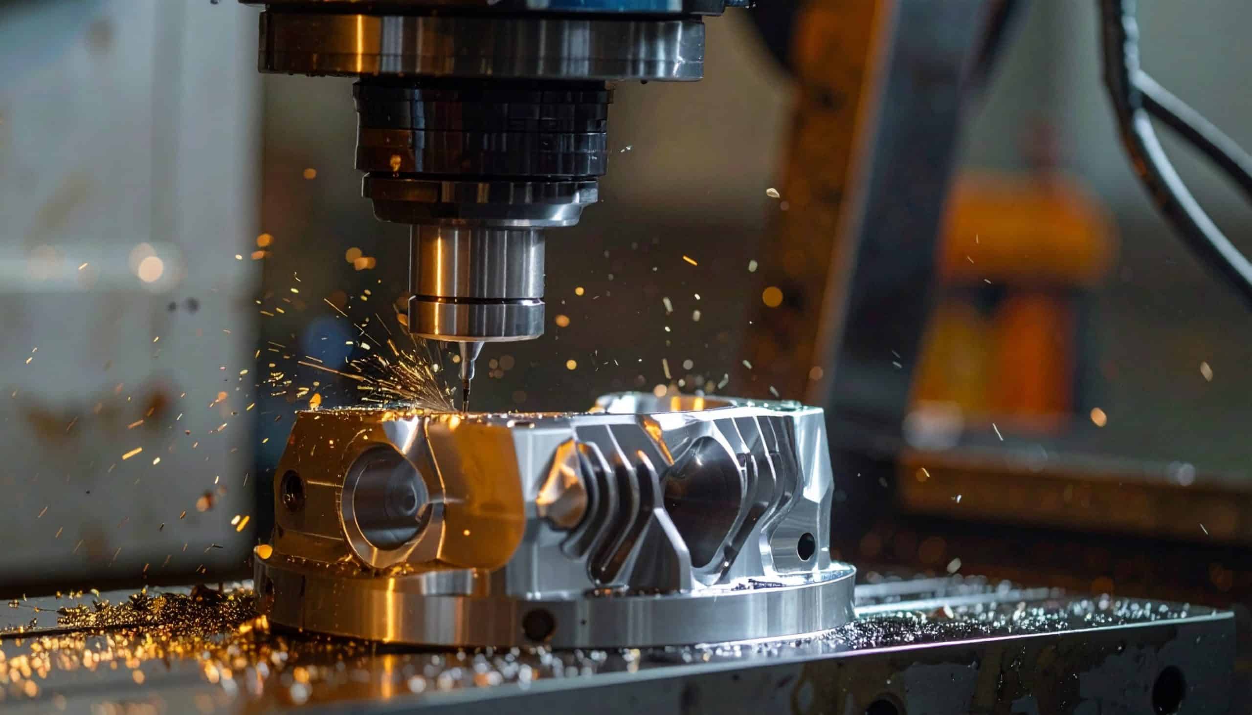
Mold and die machining is unforgiving about one thing above almost everything else: surface finish. A mold that leaves witness lines, tool marks, or surface texture variation transfers those imperfections to every part it produces. Cleaning that up downstream, whether through hand polishing or re-machining, is time that should have been eliminated at the tooling stage. When the finish is right coming off the machine, the mold ships on time and the production run starts clean.
Getting there consistently requires tooling built for the specific challenges mold and die work creates: deep cavities where tool deflection and reach compromise edge control, complex three-dimensional surfaces where scallop height and step-over relationships must be managed precisely, and hardened materials often above 50 HRC where the carbide grade and coating need to perform in conditions that general-purpose end mills are not designed for.
The challenge of deep cavities
Deep cavities in mold work put three forces against each other: tool length, rigidity, and cutting performance. Longer reach requires a longer tool, which increases deflection under cutting forces. Deflection translates to dimensional error and surface finish variation, and in the worst case it produces chatter that leaves marks the finish pass cannot remove.
The tooling response to deep cavity work is not simply to use a longer tool. It is to use the shortest tool that can reach the feature with the appropriate approach, which in many cases means a tapered reach or reduced neck design that keeps the cross-section at the cutting zone as large as possible while providing the clearance the geometry requires. Every unnecessary millimeter of tool extension adds to the deflection problem. Getting this right requires knowing the actual geometry of the cavity, not just the nominal depth, because clearance angles and sidewall draft affect what the tool can access without interference.
Ball nose tools are the standard for complex three-dimensional surfaces in mold work, but the relationship between radius, step-over, and surface finish is where production consistency lives or dies. A larger radius reduces scallop height for a given step-over but changes how the tool behaves in steep-wall sections of the cavity. Matching the ball nose radius to the steepest feature angle in the cavity ensures that finish performance stays consistent across the full surface, not just in the flat regions.

Hard milling: machining after heat treatment
The shift toward hard milling, machining mold steel in the hardened condition rather than semi-finishing and then finishing after heat treat, is well-established in modern mold shops. The advantages are real: eliminating heat treatment distortion as a source of dimensional error, reducing the number of setups, and in many cases improving
surface finish by machining in a condition where the material is more stable.
Hard milling at 50 to 65 HRC puts specific demands on the tooling. Carbide grade needs the right balance of hardness and toughness for interrupted cuts in hard material. Coating matters more than in general-purpose work: TiAlN and AlCrN are the coatings of choice for hardened tool steel because of their thermal resistance at the conditions hard milling generates. Edge prep is critical. The edge geometry that works in annealed steel will chip in the hardened equivalent, and chipping in a finishing pass on a mold cavity is a serious problem to recover from.
Feed per tooth in hard milling is often lower than machinists expect. The cutting action in very hard material is precise and controlled rather than aggressive. The goal is to maintain a consistent chip load that removes material cleanly without overloading the edge. Getting this parameter wrong produces either excessive wear from too-heavy a chip load, or rubbing and work-hardening from too-light a chip load, and both are hard to recover from in a finishing operation.
Surface finish in the finishing pass
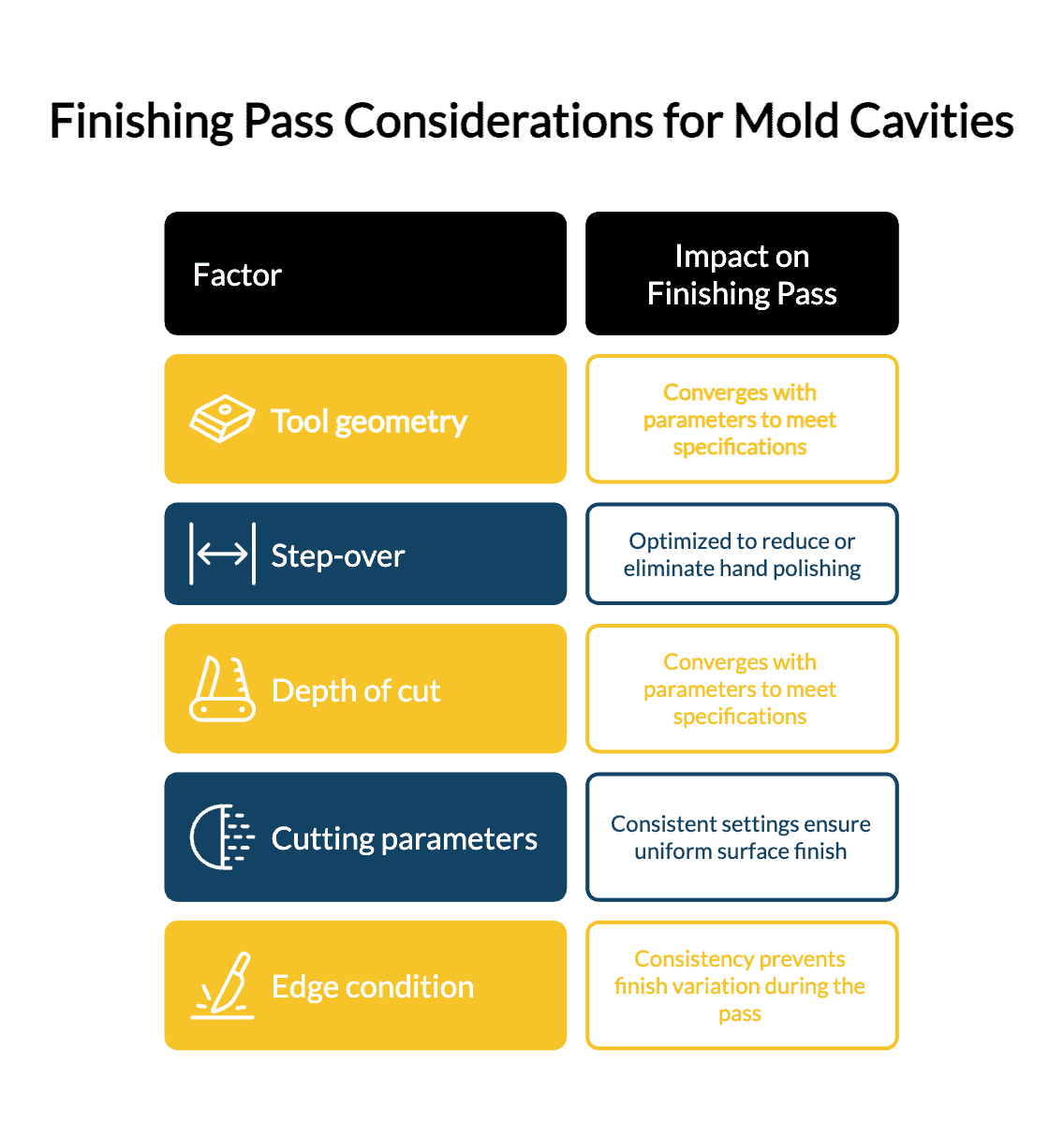
The finishing pass in a mold cavity is doing two things simultaneously: hitting final dimension and delivering the surface finish the mold specification requires. This is where tool geometry, step-over, depth of cut, and cutting parameters all converge. If any one of them is wrong, the finish suffers, and re-finishing a hardened mold cavity is both expensive and time-consuming.
High feed milling cutters are a common choice for roughing and semi-finishing in mold work because of their material removal rate at low axial depth, but they are not a finishing solution for complex three-dimensional surfaces. Ball nose end mills with appropriate radii, optimized step-over, and consistent cutting parameters are the path to a finish pass that reduces or eliminates hand polishing.
Consistency of edge condition throughout the finishing pass matters significantly. A tool that wears noticeably during the finishing operation produces a finish that varies from the start of the pass to the end. Knowing the expected tool life in your specific material and planning tool changes accordingly is part of running a mold shop at a professional level.
Material-specific tooling for mold steels
The materials in mold and die work are not uniform. P20, H13, and S7 tool steels each machine differently, and hardened H13 at 50 HRC requires different tooling decisions than P20 at 30 HRC. Beryllium copper, used for heat transfer inserts and high-conductivity mold components, requires a different approach entirely: it machines relatively easily but adheres to standard coatings, so DLC coatings or uncoated high-positive geometry is usually the right choice.
Knowing which material you are cutting is not enough on its own. Knowing the grade and the hardness of that material affects which carbide grade and coating will deliver the best result. This is exactly where the gap between a catalog selection and a purpose-built tool becomes visible in production outcomes.
What Epic Tool manufactures for mold and die work
Epic Tool has been manufacturing tooling for the mold and die making industry since 2005. This includes ball nose tools, high feed solid carbide end mills in various lengths and radius configurations, and custom geometries for applications where a standard catalog selection does not match the part requirements.
We manufacture at our facility in Stoney Creek, Ontario, using 5 and 6-axis CNC grinding equipment that produces the geometries mold work requires. We are ISO 9001:2015 certified. If you are running into surface finish or tool life problems on a specific mold application, contact our team. The faster solution is usually a conversation about the specific job rather than another round of trial and error with catalog options.